
Basic electrical symbols are standardized graphical signs used to represent electrical components in wiring diagrams, circuit schematics, and engineering drawings. They help electricians, engineers, students, and HVAC technicians understand circuits quickly without lengthy written descriptions. Common examples include battery symbols, switches, resistors, capacitors, transformers, motors, fuses, and grounding symbols.
Whether you’re reading a wiring diagram, studying electrical engineering, working on an HVAC system, or troubleshooting an electrical circuit, understanding basic electrical symbols is essential. These internationally recognized symbols simplify complex electrical drawings and ensure everyone interprets a circuit the same way.
Instead of writing the name of every component, engineers use standardized symbols defined by organizations such as IEC and ANSI. From batteries and switches to transformers and motors, each symbol has a specific meaning and purpose.
Related Post: Florida Symbols
Basic Electrical Symbols at a Glance
| Symbol Category | Examples |
| Power Sources | Battery, Cell, AC Supply, DC Supply |
| Ground Symbols | Earth Ground, Chassis Ground, Signal Ground |
| Wire & Connections | Junction, Terminal, Connector |
| Switches | SPST, SPDT, Push Button, Toggle Switch |
| Resistors | Fixed Resistor, Potentiometer, Thermistor |
| Capacitors | Fixed, Polarized, Variable Capacitor |
| Inductors | Air-Core, Iron-Core, Ferrite-Core |
| Transformers | Transformer, CT, PT, Auto Transformer |
| Protection | Fuse, Circuit Breaker, SPD |
| HVAC Symbols | Thermostat, Compressor, Contactor |
What Are Basic Electrical Symbols?
Electrical symbols are simple graphical representations of electrical components used in schematics and wiring diagrams. Instead of drawing the physical appearance of a device, engineers use standardized symbols that make drawings easier to read and universally understood.
These symbols are commonly found in:
- Residential wiring diagrams
- Commercial electrical plans
- Industrial control panels
- HVAC schematics
- PLC diagrams
- Electronic circuit boards
- Engineering blueprints
Because they follow international standards, the same symbol can usually be recognized by electricians and engineers around the world.
Power Source Symbols
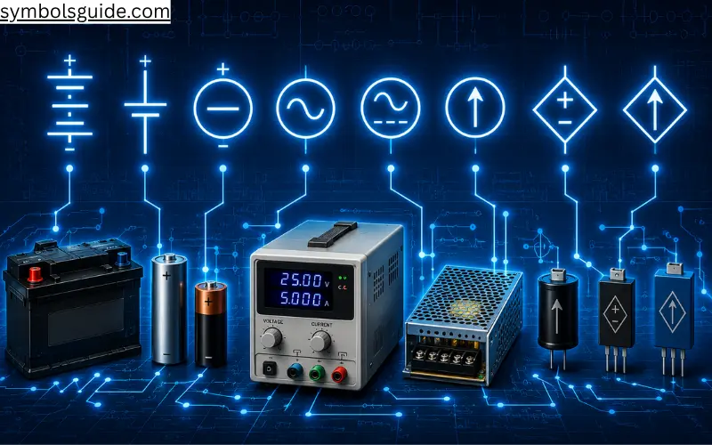
Power source symbols represent components that supply electrical energy to a circuit.
Battery
The battery symbol consists of alternating long and short parallel lines that represent multiple cells connected together. It is commonly used in portable electronics, emergency lighting systems, and automotive circuits.
Cell
A cell symbol represents a single electrochemical power source. It is typically used in educational circuit diagrams and small electronic devices powered by one battery cell.
DC Voltage Source
The DC voltage source symbol identifies a direct current supply where electricity flows in one direction. It is widely used in electronic circuits, solar power systems, and battery-operated equipment.
AC Voltage Source
This symbol represents an alternating current power supply. It appears in residential wiring diagrams, industrial electrical systems, and utility power distribution schematics.
AC/DC Supply
The AC/DC supply symbol indicates equipment capable of operating with either alternating current or direct current. It is commonly found in adapters, chargers, and dual-power electronic devices.
Current Source
A current source provides a constant current regardless of voltage changes within its operating limits. It is frequently used in electronic design and circuit analysis.
Controlled Voltage Source
This symbol represents a voltage source controlled by another electrical signal. It commonly appears in advanced electronic and engineering schematics.
Controlled Current Source
A controlled current source delivers output current based on another circuit variable. It is primarily used in electronic simulations and complex analog circuit designs.
Power Source Symbols Overview
| Symbol | Common Use |
| Battery | Portable Power |
| Cell | Single Power Source |
| DC Supply | Electronics |
| AC Supply | Residential Wiring |
| AC/DC Supply | Power Adapters |
| Current Source | Circuit Design |
| Controlled Voltage Source | Analog Circuits |
| Controlled Current Source | Electronic Systems |
Ground Symbols
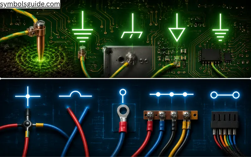
Ground symbols provide a common reference point for electrical circuits and improve safety by directing unwanted electrical current away from equipment and users.
Earth Ground
The Earth Ground symbol represents a direct connection to the earth. It protects electrical systems from faults, lightning strikes, and electrical leakage. It is one of the most common symbols in residential and industrial wiring diagrams.
Chassis Ground
The Chassis Ground symbol indicates that a component is connected to the metal frame of equipment instead of directly to earth. It helps reduce electrical shock risks and improves equipment safety.
Signal Ground
Signal Ground provides a stable reference point for low-voltage electronic signals. It is commonly used in audio equipment, communication devices, and electronic control systems to minimize electrical noise.
Digital Ground
Digital Ground is used in digital circuits and microcontroller systems. Separating digital and analog grounds helps improve circuit performance and reduces interference.
Ground Symbols Overview
| Symbol | Primary Use |
| Earth Ground | Electrical Safety |
| Chassis Ground | Equipment Protection |
| Signal Ground | Electronic Circuits |
| Digital Ground | Digital Systems |
Wire & Connection Symbols
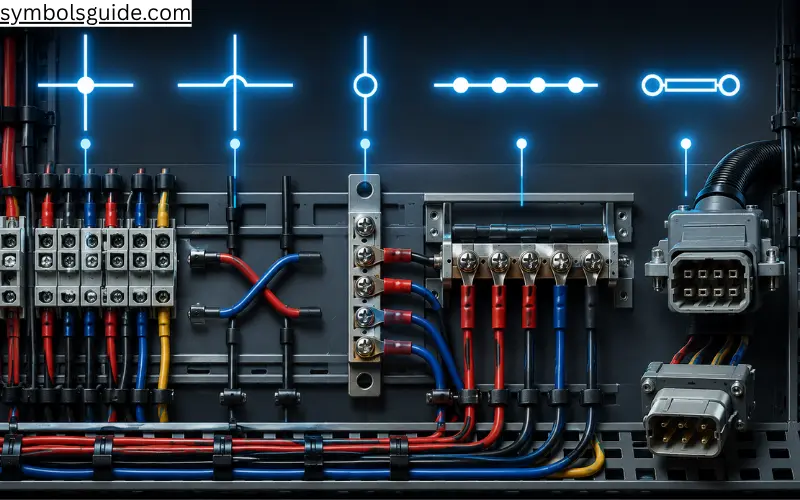
Wire symbols illustrate how electrical components are connected within a circuit. Understanding these symbols is essential when reading wiring diagrams and electrical schematics.
Connected Wires
This symbol shows two or more wires electrically joined at a junction. It allows electricity to flow between connected conductors.
Crossing Wires (Not Connected)
When two wires cross without a junction dot, they are not electrically connected. This symbol prevents confusion in complex circuit diagrams.
Terminal
A terminal symbol represents the point where a wire connects to a device, connector, or electrical component.
Bus Line
A bus line carries electrical power or signals to multiple circuits. It is commonly found in switchboards, industrial control panels, and power distribution systems.
Connector
The connector symbol identifies a removable electrical connection between two cables or devices. Connectors simplify maintenance and equipment replacement.
Wire & Connection Symbols Overview
| Symbol | Common Application |
| Connected Wires | Circuit Junction |
| Crossing Wires | Separate Conductors |
| Terminal | Connection Point |
| Bus Line | Power Distribution |
| Connector | Cable Connections |
Switch Symbols
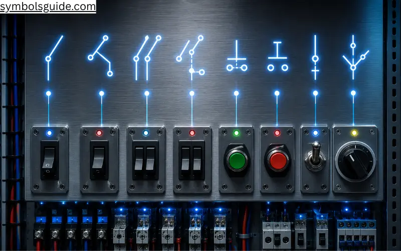
Switch symbols represent devices that open, close, or redirect electrical current. They are among the most frequently used symbols in electrical diagrams.
SPST Switch (Single Pole Single Throw)
The SPST switch controls a single electrical circuit using one ON/OFF position. It is commonly found in lighting circuits and household appliances.
SPDT Switch (Single Pole Double Throw)
An SPDT switch allows one input to connect to either of two outputs. It is widely used for changeover circuits and signal routing.
DPST Switch (Double Pole Single Throw)
A DPST switch simultaneously controls two separate circuits using one switching action. It is often used for disconnecting both live and neutral conductors.
DPDT Switch (Double Pole Double Throw)
The DPDT switch controls two independent circuits while allowing each to switch between two outputs. It is commonly used in motor reversing circuits.
Normally Open Push Button
A Normally Open (NO) push button completes the circuit only when pressed. It is commonly used for start buttons and doorbells.
Normally Closed Push Button
A Normally Closed (NC) push button interrupts the circuit when pressed. Emergency stop systems frequently use this symbol.
Toggle Switch
The toggle switch changes between ON and OFF positions using a mechanical lever. It is commonly found in control panels and household equipment.
Selector Switch
A selector switch allows operators to choose between multiple operating modes or circuit paths. It is widely used in industrial machinery and electrical control panels.
Switch Symbols Overview
| Symbol | Typical Use |
| SPST Switch | Basic ON/OFF Control |
| SPDT Switch | Changeover Circuits |
| DPST Switch | Dual Circuit Switching |
| DPDT Switch | Motor Control |
| NO Push Button | Start Function |
| NC Push Button | Emergency Stop |
| Toggle Switch | Manual Control |
| Selector Switch | Mode Selection |
Protection Symbols
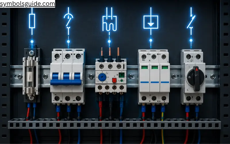
Protection devices safeguard electrical systems against overloads, short circuits, and voltage surges.
Fuse
A fuse contains a thin metal element that melts when excessive current flows, preventing damage to electrical equipment.
Circuit Breaker
Unlike a fuse, a circuit breaker can be reset after it trips. It automatically disconnects power during overloads or short circuits.
Thermal Overload Relay
Thermal overload relays protect electric motors from overheating by disconnecting power when excessive current persists.
Surge Protection Device (SPD)
An SPD protects electrical equipment from voltage spikes caused by lightning strikes or switching events.
Isolator Switch
An isolator switch disconnects equipment from its power source for safe maintenance and servicing.
Protection Symbols Overview
| Symbol | Purpose |
| Fuse | Overcurrent Protection |
| Circuit Breaker | Automatic Circuit Protection |
| Thermal Overload Relay | Motor Protection |
| Surge Protection Device | Voltage Surge Protection |
| Isolator Switch | Safe Equipment Isolation |
Resistor Symbols
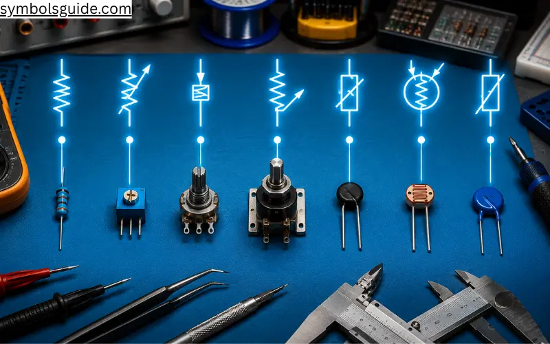
Resistors control the flow of electrical current by limiting resistance within a circuit. They are among the most commonly used components in electrical and electronic systems.
Fixed Resistor
A fixed resistor provides a constant resistance value that cannot be adjusted. It is widely used in household electronics, control boards, and power supplies.
Variable Resistor
A variable resistor allows resistance to be adjusted manually. It is commonly used to control voltage and current in electronic circuits.
Potentiometer
A potentiometer is a three-terminal variable resistor used to adjust voltage. It is often found in audio volume controls, dimmer switches, and electronic equipment.
Rheostat
A rheostat controls current by varying resistance through two terminals. It is commonly used for motor speed control and lighting applications.
Thermistor
A thermistor changes its resistance according to temperature. It is widely used in HVAC systems, temperature sensors, and battery protection circuits.
Light Dependent Resistor (LDR)
An LDR, also known as a photoresistor, changes resistance based on light intensity. It is commonly used in automatic lighting systems and security devices.
Varistor (MOV)
A Metal Oxide Varistor protects electrical equipment by absorbing sudden voltage spikes. It is commonly installed in surge protectors and power distribution equipment.
Resistor Symbols Overview
| Symbol | Typical Application |
| Fixed Resistor | General Circuits |
| Variable Resistor | Adjustable Circuits |
| Potentiometer | Volume & Voltage Control |
| Rheostat | Current Control |
| Thermistor | Temperature Sensing |
| LDR | Light Detection |
| Varistor | Surge Protection |
Capacitor Symbols
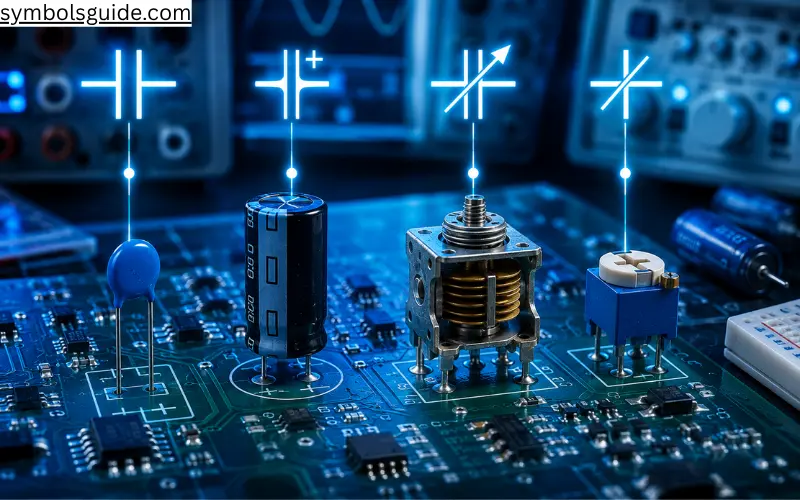
Capacitors store electrical energy temporarily and release it when required. They are widely used for filtering, timing, starting motors, and smoothing voltage.
Fixed Capacitor
A fixed capacitor stores a constant amount of electrical charge. It appears in nearly every electronic device.
Polarized Capacitor
Polarized capacitors have positive and negative terminals and are mainly used in DC power supplies and electronic circuits.
Variable Capacitor
A variable capacitor allows capacitance to be adjusted. It is commonly found in radio tuning circuits and communication equipment.
Trimmer Capacitor
A trimmer capacitor is a small adjustable capacitor used for precise circuit calibration during manufacturing or servicing.
Capacitor Symbols Overview
| Symbol | Common Use |
| Fixed Capacitor | Energy Storage |
| Polarized Capacitor | DC Filtering |
| Variable Capacitor | Frequency Tuning |
| Trimmer Capacitor | Circuit Calibration |
Inductor Symbols
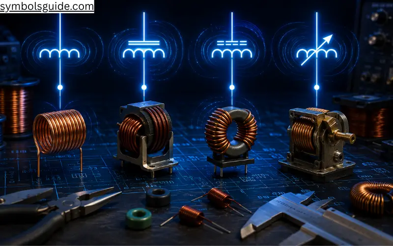
Inductors store energy in a magnetic field and help regulate current flow. They are commonly used in power supplies, filters, transformers, and radio-frequency circuits.
Air-Core Inductor
An air-core inductor has no magnetic core and is commonly used in high-frequency electronic circuits.
Iron-Core Inductor
Iron-core inductors provide higher inductance and are often used in power supplies and industrial electrical equipment.
Ferrite-Core Inductor
Ferrite-core inductors reduce energy losses at high frequencies, making them common in switching power supplies and communication devices.
Variable Inductor
A variable inductor allows inductance to be adjusted for tuning and calibration purposes in specialized electronic circuits.
Inductor Symbols Overview
| Symbol | Common Application |
| Air-Core Inductor | RF Circuits |
| Iron-Core Inductor | Power Systems |
| Ferrite-Core Inductor | High-Frequency Electronics |
| Variable Inductor | Circuit Tuning |
Transformer Symbols
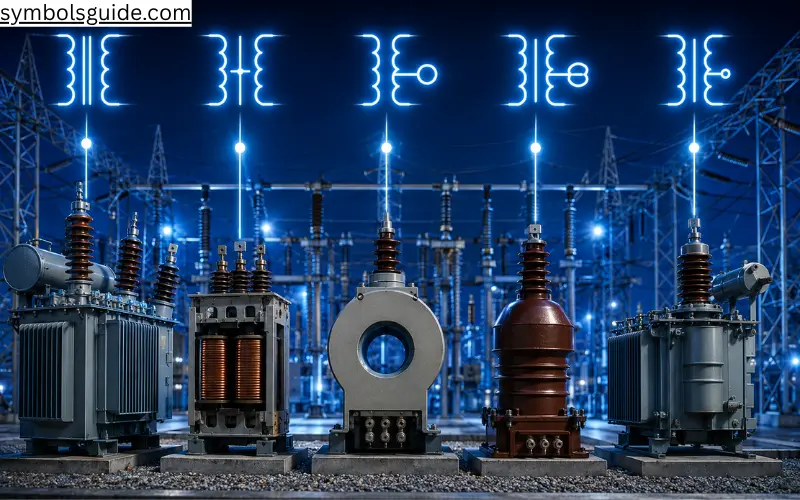
Transformers transfer electrical energy between circuits through electromagnetic induction. They are essential in power distribution, industrial systems, and HVAC equipment.
Transformer
The standard transformer symbol represents two magnetically coupled coils that increase or decrease voltage.
Center-Tapped Transformer
A center-tapped transformer provides multiple output voltages from a single secondary winding and is commonly used in power supply circuits.
Current Transformer (CT)
Current transformers safely reduce high electrical current for measurement and protection systems. They are widely used in industrial switchgear.
Potential Transformer (PT)
Potential transformers lower high voltages to safe levels for meters and protective relays without affecting circuit accuracy.
Auto Transformer
An autotransformer uses a single winding with shared input and output connections. It is commonly used for voltage regulation and motor starting applications.
Transformer Symbols Overview
| Symbol | Typical Application |
| Transformer | Voltage Conversion |
| Center-Tapped Transformer | Dual Output Power Supply |
| Current Transformer (CT) | Current Measurement |
| Potential Transformer (PT) | Voltage Measurement |
| Auto Transformer | Voltage Regulation |
Diode Symbols
Diodes allow electrical current to flow in one direction while blocking it in the opposite direction. They are essential components in power supplies, signal processing, and protection circuits.
Standard Diode
The standard diode is used for AC-to-DC rectification and current control in electronic circuits.
Zener Diode
A Zener diode maintains a constant output voltage and is commonly used in voltage regulation circuits.
Light Emitting Diode (LED)
An LED converts electrical energy into light. It is widely used in indicators, displays, lighting systems, and electronic devices.
Photodiode
A photodiode detects light and converts it into an electrical signal. It is commonly found in sensors, remote controls, and optical communication systems.
Schottky Diode
Schottky diodes have a low forward voltage drop and fast switching speed, making them ideal for power supplies and high-speed circuits.
Bridge Rectifier
A bridge rectifier converts alternating current (AC) into direct current (DC) using four interconnected diodes.
Diode Symbols Overview
| Symbol | Primary Application |
| Standard Diode | Rectification |
| Zener Diode | Voltage Regulation |
| LED | Lighting & Indicators |
| Photodiode | Light Detection |
| Schottky Diode | High-Speed Switching |
| Bridge Rectifier | AC to DC Conversion |
Transistor Symbols
Transistors act as electronic switches and amplifiers. They are fundamental building blocks of modern electronic circuits.
NPN Transistor
The NPN transistor is the most commonly used bipolar junction transistor for switching and amplification.
PNP Transistor
A PNP transistor operates similarly to an NPN transistor but uses opposite current flow and polarity.
N-Channel MOSFET
N-channel MOSFETs provide efficient high-speed switching in power electronics and motor control systems.
P-Channel MOSFET
P-channel MOSFETs are commonly used for high-side switching applications and power management circuits.
Transistor Symbols Overview
| Symbol | Common Use |
| NPN Transistor | Switching |
| PNP Transistor | Amplification |
| N-Channel MOSFET | Power Electronics |
| P-Channel MOSFET | High-Side Switching |
Relay & Control Symbols
Relay symbols represent electrically operated switches that automate circuit control in industrial, commercial, and HVAC systems.
Relay Coil
The relay coil creates a magnetic field that opens or closes electrical contacts when energized.
Normally Open (NO) Relay Contact
A normally open contact remains disconnected until the relay coil is energized.
Normally Closed (NC) Relay Contact
A normally closed contact remains connected until the relay activates.
Contactor
A contactor is a heavy-duty relay designed for controlling electric motors, compressors, and large electrical loads.
Relay Symbols Overview
| Symbol | Typical Application |
| Relay Coil | Automatic Switching |
| NO Contact | Start Circuits |
| NC Contact | Safety Circuits |
| Contactor | Motor & HVAC Control |
Motor & Generator Symbols
Motor symbols identify equipment that converts electrical energy into mechanical motion, while generators perform the opposite function.
AC Motor
An AC motor operates on alternating current and is commonly used in household appliances and industrial machinery.
DC Motor
DC motors are widely used in battery-powered equipment, robotics, and automotive systems.
Three-Phase Motor
Three-phase motors deliver high efficiency and are commonly installed in factories, manufacturing plants, and commercial HVAC systems.
Generator
Generators convert mechanical energy into electrical energy and serve as backup or primary power sources.
Motor Symbols Overview
| Symbol | Common Application |
| AC Motor | Residential Equipment |
| DC Motor | Portable Devices |
| Three-Phase Motor | Industrial Machinery |
| Generator | Power Generation |
Measuring Instrument Symbols
Electrical measuring instruments help technicians monitor voltage, current, resistance, and power during installation and troubleshooting.
Voltmeter
Measures electrical voltage across two points in a circuit.
Ammeter
Measures the flow of electrical current through a conductor.
Ohmmeter
Measures the electrical resistance of components and wiring.
Wattmeter
Measures electrical power consumption in a circuit.
Measuring Instrument Symbols Overview
| Symbol | Measures |
| Voltmeter | Voltage |
| Ammeter | Current |
| Ohmmeter | Resistance |
| Wattmeter | Power |
HVAC Electrical Symbols
HVAC electrical symbols are used in heating, ventilation, and air conditioning wiring diagrams. Understanding these symbols helps technicians install, troubleshoot, and repair HVAC systems safely.
Thermostat
Controls heating and cooling equipment by monitoring room temperature.
Compressor
Represents the main refrigeration component responsible for circulating refrigerant.
Condenser Fan Motor
Drives the outdoor fan that removes heat from the condenser coil.
Blower Motor
Moves conditioned air through ductwork and indoor spaces.
Pressure Switch
Protects HVAC equipment by monitoring refrigerant or air pressure.
Disconnect Switch
Provides a safe method for isolating HVAC equipment during maintenance.
Run Capacitor
Stores electrical energy to improve the starting and running efficiency of motors.
24-Volt Control Transformer
Reduces line voltage to low-voltage control power for thermostats and HVAC control circuits.
HVAC Electrical Symbols Overview
| Symbol | Primary Function |
| Thermostat | Temperature Control |
| Compressor | Refrigeration |
| Condenser Fan Motor | Heat Rejection |
| Blower Motor | Air Circulation |
| Pressure Switch | System Protection |
| Disconnect Switch | Equipment Isolation |
| Run Capacitor | Motor Starting |
| 24V Transformer | Low-Voltage Control |
Printable Basic Electrical Symbols Chart
| Category | Examples |
| Power Sources | Battery, Cell, AC Supply, DC Supply |
| Ground | Earth, Chassis, Signal, Digital |
| Connections | Junction, Terminal, Connector |
| Switches | SPST, SPDT, DPST, DPDT |
| Protection | Fuse, Circuit Breaker, SPD |
| Passive Components | Resistor, Capacitor, Inductor |
| Transformers | CT, PT, Auto Transformer |
| Semiconductors | Diode, LED, MOSFET |
| Motors | AC Motor, DC Motor, Generator |
| HVAC | Thermostat, Compressor, Blower Motor |
See Also
- 77+ Autumn Symbols: Meanings, Myths & Traditions
- 72+ Timeless Leadership Symbols From Royalty and History
- Sacred Healing Symbols From Ancient Traditions Around the World
- 50+ Sacred Voodoo Symbols From Haitian & New Orleans
- 35+ Official Florida Symbols That Represent the Sunshine State
FAQs
What are basic electrical symbols?
Basic electrical symbols are standardized drawings that represent electrical components in wiring diagrams and circuit schematics.
Why are electrical symbols important?
They provide a universal language that allows electricians, engineers, and technicians to read electrical drawings accurately.
Which standards define electrical symbols?
Most electrical symbols follow IEC (International Electrotechnical Commission) or ANSI/IEEE standards, depending on the region and industry.
Where are electrical symbols used?
They are used in residential wiring, industrial control panels, electronic circuits, HVAC systems, engineering blueprints, and electrical schematics.
What is the most common electrical symbol?
The battery, resistor, switch, ground, fuse, and transformer symbols are among the most frequently used in electrical diagrams.
What are HVAC electrical symbols?
HVAC electrical symbols represent components such as thermostats, compressors, blower motors, contactors, transformers, and pressure switches used in heating and cooling systems.
Can beginners learn electrical symbols easily?
Yes. Once you understand the basic categories—power sources, switches, protection devices, passive components, and motors—reading electrical diagrams becomes much easier.
Conclusion
Learning basic electrical symbols is one of the first steps toward understanding electrical wiring diagrams, circuit schematics, and engineering drawings. Whether you’re a student, electrician, engineer, or HVAC technician, these standardized symbols make complex circuits easier to read, troubleshoot, and design.
By organizing symbols into practical categories such as power sources, switches, protection devices, transformers, motors, and HVAC components, you can quickly identify electrical equipment and interpret professional diagrams with confidence. Keep this guide as a reference whenever you work with electrical plans or circuit diagrams.