Digital logic symbols are standardized visual representations that show how digital circuits process, store, control, and transfer binary data using gates, memory elements, counters, registers, and other electronic components.
From smartphones and computers to embedded systems and robotics, digital logic symbols provide a universal language that helps engineers design, analyze, and understand modern digital circuits efficiently.
Related Post: Strong Woman Symbols
Most Common Digital Logic Symbols at a Glance
| Symbol | Meaning |
| AND Gate | Logical multiplication |
| OR Gate | Logical addition |
| NOT Gate | Signal inversion |
| NAND Gate | Universal logic gate |
| NOR Gate | Universal logic gate |
| XOR Gate | Exclusive comparison |
| XNOR Gate | Equality detection |
| Buffer | Signal isolation |
| Multiplexer | Data selection |
| D Flip-Flop | Data storage |
Why Digital Logic Symbols Matter
| Benefit | Why It Matters |
| Circuit Design | Simplifies complex electronic systems |
| Communication | Creates a universal engineering language |
| Troubleshooting | Helps identify circuit functions quickly |
| Documentation | Standardizes technical schematics |
| Learning | Makes digital systems easier to understand |
Basic Logic Gate Symbols
1. AND Gate Symbol
The AND gate produces an output only when every input is active. It is commonly used in decision-making circuits where multiple conditions must be satisfied simultaneously.
2. OR Gate Symbol
The OR gate generates an output whenever at least one input becomes active. It is widely used for combining multiple decision paths.
3. NOT Gate Symbol
Also called an inverter, the NOT gate reverses a signal’s logical state, turning HIGH into LOW and LOW into HIGH.
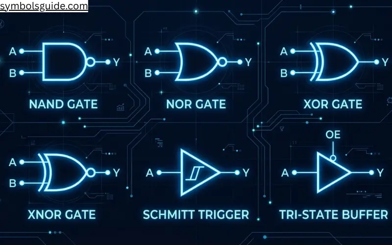
4. NAND Gate Symbol
The NAND gate combines AND logic with inversion. Because any digital circuit can be constructed from NAND gates alone, it is considered a universal gate.
5. NOR Gate Symbol
The NOR gate combines OR logic with inversion and is another universal gate frequently used in memory and control circuits.
6. XOR Gate Symbol
The Exclusive OR gate activates only when its inputs differ, making it valuable for comparison and error-detection applications.
7. XNOR Gate Symbol
The XNOR gate indicates logical equality by producing an active output whenever compared inputs match.
8. Buffer Symbol
A buffer passes a signal unchanged while improving signal strength and isolating connected circuit sections.
9. Inverting Buffer Symbol
This symbol combines signal buffering and inversion into a single logic element.
10. Tri-State Buffer Symbol
A tri-state buffer can output HIGH, LOW, or High-Impedance states, allowing multiple devices to share communication lines safely.
Signal Conditioning and Control Symbols
11. Schmitt Trigger Symbol
The Schmitt Trigger improves switching reliability by reducing noise and preventing false transitions.
12. Inverting Schmitt Trigger Symbol
This symbol combines hysteresis-based noise filtering with logical inversion.
13. Transmission Gate Symbol
A transmission gate functions as a controlled electronic switch capable of passing digital signals efficiently.
14. Open-Collector Symbol
Open-collector outputs require external pull-up resistors and are widely used in shared communication networks.
15. Open-Drain Symbol
Open-drain outputs are common in embedded systems and serial communication protocols such as I²C.
16. Enable Symbol
The enable symbol indicates that a device becomes operational only when a control signal is active.
17. Clock Symbol
The clock symbol synchronizes operations throughout digital systems and sequential circuits.
18. Reset Symbol
A reset signal forces a digital device into a predefined starting condition.
19. Preset Symbol
The preset symbol initializes a memory element into a predefined active state.
20. Clear Symbol
The clear symbol immediately removes stored data or forces outputs into a default condition.
Data Routing Symbols
21. Multiplexer (MUX) Symbol
A multiplexer selects one input from several available signals and forwards it to a single output.
22. Demultiplexer (DEMUX) Symbol
The demultiplexer routes a single input signal toward one of several outputs.
23. Decoder Symbol
A decoder converts binary inputs into unique output lines for selection and addressing operations.
24. Encoder Symbol
An encoder converts multiple inputs into a compact binary representation.
25. Priority Encoder Symbol
A priority encoder ensures that the highest-priority active input receives processing preference when multiple signals occur simultaneously.
Comparator Symbols
26. Comparator Symbol
The comparator symbol checks whether two binary values are equal, greater than, or less than each other. It plays an important role in processors, controllers, and digital decision-making circuits.
27. ROM Symbol
Commonly found in firmware, lookup tables, and embedded controllers, ROM stores permanent instructions that remain available even after power is removed.
28. RAM Symbol
Modern processors use RAM to temporarily store active data and program instructions for fast access during operation.
29. SRAM Symbol
Digital designers rely on SRAM for processor caches because it delivers extremely fast access speeds while retaining data as long as power is available.
30. DRAM Symbol
Dynamic Random Access Memory stores data using capacitors that require periodic refreshing. It is commonly used as the main memory in computers and digital devices.
Latch Symbols
31. SR Latch Symbol
This circuit helps store a single binary bit and serves as one of the earliest forms of digital memory.
32. NAND SR Latch Symbol
Often appears in introductory digital electronics because it demonstrates how memory can be created using logic gates.
33. NOR SR Latch Symbol
Digital designers rely on NOR-based latches when studying fundamental memory architectures.
34. D Latch Symbol
Embedded systems depend on D latches for temporary data storage and signal synchronization.
35. Transparent Latch Symbol
This device allows input data to pass directly to the output whenever the enable signal remains active.
Flip-Flop Symbols
36. D Flip-Flop Symbol
Modern processors use D Flip-Flops extensively for storing and synchronizing digital information.
37. JK Flip-Flop Symbol
Engineers use this symbol to represent one of the most versatile memory elements in sequential logic design.
38. T Flip-Flop Symbol
The T Flip-Flop changes state each time a triggering clock pulse arrives, making it useful in counters.
39. Master-Slave Flip-Flop Symbol
This symbol represents a two-stage memory device designed to improve timing accuracy and reduce race conditions.
40. Edge-Triggered Flip-Flop Symbol
An edge-triggered Flip-Flop changes state only during a specific clock transition.
41. FIFO Symbol
Commonly found in communication hardware, networking equipment, and buffering circuits, FIFO (First-In First-Out) memory ensures that data leaves in the same order it enters the system.
42. Barrel Shifter Symbol
Modern processors use Barrel Shifters to perform high-speed bit shifting and rotation operations in a single clock cycle, improving arithmetic and data-processing performance.
43. Asynchronous Set Flip-Flop Symbol
The asynchronous set input forces a stored HIGH state immediately, regardless of clock activity, making it useful for initialization and recovery functions.
44. Asynchronous Reset Flip-Flop Symbol
Engineers use this symbol to clear stored data instantly without waiting for the next clock pulse.
45. Synchronous Flip-Flop Symbol
Digital designers rely on synchronous Flip-Flops when predictable clock-controlled operation is required throughout a system.
Register Symbols
46. Register Symbol
A register consists of multiple Flip-Flops working together to store binary information temporarily.
47. Shift Register Symbol
The shift register moves stored data from one storage position to another during clock operations.
48. Serial-In Serial-Out Register Symbol
This register accepts and outputs data one bit at a time, making it suitable for serial communication.
49. Serial-In Parallel-Out Register Symbol
A Serial-In Parallel-Out register converts incoming serial data into parallel outputs for faster processing.
50. Parallel-In Serial-Out Register Symbol
This symbol represents a register that accepts multiple bits simultaneously and transmits them serially.
Digital Memory Symbols at a Glance
| Symbol Category | Examples |
| Memory Devices | ROM, RAM, SRAM, DRAM |
| Latches | SR Latch, D Latch |
| Flip-Flops | D, JK, T |
| Registers | Shift Register, SISO, SIPO, PISO |
| Storage Buffers | FIFO |
Advanced Register Symbols
51. Parallel-In Parallel-Out Register Symbol
This register accepts multiple bits simultaneously and outputs them in parallel, making it useful for high-speed data storage and transfer.
52. Universal Shift Register Symbol
The universal shift register supports serial input, serial output, parallel loading, and bidirectional shifting within a single device.
53. Bidirectional Shift Register Symbol
This register can move stored data either left or right depending on the selected control signal.
54. Ring Register Symbol
A ring register circulates a single active bit continuously through a chain of Flip-Flops.
55. EEPROM Symbol
Engineers use EEPROM to store configuration settings and firmware data that must survive power loss while remaining electrically reprogrammable.
Counter Symbols
56. Counter Symbol
The counter symbol represents a circuit designed to count pulses, events, or clock cycles.
57. Binary Counter Symbol
A binary counter progresses through a sequence of binary numbers as clock pulses arrive.
58. Up Counter Symbol
An up counter increases its stored value by one during each valid counting event.
59. Down Counter Symbol
The down counter decreases its value step by step as clock signals are received.
60. Up-Down Counter Symbol
This counter can count upward or downward depending on a control input.
61. Ripple Counter Symbol
A ripple counter passes clock transitions through sequential stages, creating a simple counting structure.
62. Synchronous Counter Symbol
Unlike ripple counters, all stages of a synchronous counter update simultaneously.
63. Decade Counter Symbol
A decade counter cycles through ten states before returning to its starting position.
64. Johnson Counter Symbol
The Johnson counter uses feedback connections to generate unique timing sequences.
65. Frequency Divider Symbol
A frequency divider reduces an incoming clock frequency into a lower frequency signal.
Arithmetic Logic Symbols
66. Half Adder Symbol
Engineers use the Half Adder to add two binary digits and generate both a sum output and a carry output. It serves as one of the fundamental building blocks of arithmetic circuits.
67. Full Adder Symbol
Modern processors rely on Full Adders to perform multi-bit arithmetic operations. Unlike a Half Adder, it can process an incoming carry signal from a previous stage.
68. Half Subtractor Symbol
This symbol performs subtraction between two single-bit binary values.
69. Full Subtractor Symbol
A Full Subtractor handles subtraction operations while accounting for borrow inputs.
70. Arithmetic Logic Unit (ALU) Symbol
Modern processors use the Arithmetic Logic Unit (ALU) to perform calculations, comparisons, logical decisions, and other operations required to execute software instructions. It serves as the computational core of digital systems ranging from microcontrollers to advanced CPUs.
71. Accumulator Symbol
An accumulator temporarily stores intermediate results generated during calculations.
72. Binary Multiplier Symbol
A binary multiplier handles multiplication between binary numbers and is commonly used in processors, DSP hardware, and arithmetic circuits.
73. Carry Look-Ahead Adder Symbol
The Carry Look-Ahead Adder improves processing speed by calculating carry values in advance.
74. Parity Generator Symbol
A parity generator creates parity bits used to improve error detection during data transmission.
75. Parity Checker Symbol
The parity checker checks received parity bits and helps detect errors that may occur during digital data transmission.
Digital Logic Symbols by Category
| Category | Examples |
| Logic Gates | AND, OR, NOT, NAND, NOR, XOR, XNOR |
| Signal Control | Buffer, Schmitt Trigger, Clock |
| Data Routing | Multiplexer, Demultiplexer |
| Decoding Circuits | Decoder, Encoder |
| Comparison Circuits | Comparators |
| Memory Elements | Latches, Flip-Flops |
| Storage Devices | Registers |
| Counting Circuits | Counters |
| Arithmetic Circuits | Adders, Subtractors, ALU |
| Error Detection | Parity Generator, Parity Checker |
Most Important Digital Logic Symbols
| Rank | Symbol | Main Function |
| 1 | AND Gate | Logical decision making |
| 2 | OR Gate | Combining conditions |
| 3 | NOT Gate | Signal inversion |
| 4 | NAND Gate | Universal logic implementation |
| 5 | NOR Gate | Universal logic implementation |
| 6 | XOR Gate | Difference detection |
| 7 | XNOR Gate | Equality detection |
| 8 | D Flip-Flop | Data storage |
| 9 | Multiplexer | Signal selection |
| 10 | ALU | Digital computation |
Where Digital Logic Symbols Are Used
Digital logic symbols are found throughout modern electronics and computer engineering.
Common applications include:
- Computer processors
- Smartphones
- Embedded systems
- FPGA development
- Arduino projects
- Robotics
- Industrial automation
- Networking equipment
- Communication systems
- Digital control systems
- Memory devices
- Consumer electronics
These symbols allow engineers to design, analyze, document, and troubleshoot digital systems efficiently.
Common Mistakes When Reading Digital Logic Symbols
Confusing NAND and AND Gates
A small inversion bubble completely changes circuit behavior and should never be overlooked.
Mixing XOR and OR Gates
Although their shapes appear similar, XOR detects differences while OR responds to any active input.
Ignoring Clock Signals
Sequential logic circuits depend heavily on timing and clock synchronization.
Misreading Active-Low Indicators
A small circle on an input or output changes the logic interpretation of a signal.
Overlooking Data Direction
Multiplexers, demultiplexers, registers, and counters often depend on signal flow direction.
Real-World Importance of Digital Logic Symbols
Understanding digital logic symbols is one of the first steps toward learning computer engineering, embedded systems, FPGA design, microprocessor architecture, and digital electronics.
These symbols simplify complex circuits into understandable diagrams, allowing engineers and students to visualize how data moves, how decisions are made, and how electronic devices perform computations.
Whether you are analyzing a simple Arduino project or studying advanced processor architecture, digital logic symbols remain an essential part of the engineering language.
See Also
- 100+ Holy Thursday Symbols and Meanings Explained
- 113+ One Piece Symbols and Meanings with Names
- 121+ Hanukkah Symbols and Their Meanings with Names
- 128+ Destiny Symbols and Meanings with Names
- 132+ Strong Woman Symbols and Meanings for Inspiration
FAQs
What are digital logic symbols?
Digital logic symbols are graphical representations used to describe logical operations, memory functions, arithmetic circuits, data routing, and signal control in digital electronics.
What is the difference between logic gate symbols and digital logic symbols?
Logic gate symbols represent individual gates such as AND, OR, and NOT, while digital logic symbols include gates, registers, counters, multiplexers, decoders, and memory devices.
Which gates are called universal gates?
NAND and NOR gates are universal because they can be used to construct any logical function.
Why are digital logic symbols important?
They provide a standardized visual language that engineers use to design and analyze digital circuits.
What does the small circle on a logic symbol mean?
The circle usually represents logical inversion or an active-low condition.
What is a Flip-Flop symbol?
A Flip-Flop symbol represents a memory element capable of storing one binary bit.
What is a Multiplexer symbol?
A Multiplexer selects one signal from multiple inputs and forwards it to a single output.
What is an ALU symbol?
The Arithmetic Logic Unit symbol represents the section of a processor responsible for calculations and logical operations.
Conclusion
Digital logic symbols are the building blocks of modern electronics, helping engineers design, analyze, and troubleshoot everything from simple circuits to advanced processors. By understanding these 75+ digital logic symbols and meanings, you’ll gain a clearer understanding of how computers, embedded systems, communication devices, and digital technologies work behind the scenes.